BeagleBone Black Serial UART Device Tree Overlays for Ubuntu and Debian Wheezy (tty01, tty02, tty04, tty05 .dtbo files)

BeagleBone Black UARTs

Unlike the BeagleBone White, the BeagleBone Black has no built-in serial to USB connection. This was one of the several cost saving measures taken in order to get the per-unit price down to $45 USD. The serial debug interface available at J1 is setup to allow the use of an FTDI TTL-232R-3V3 3.3V serial to USB adapter (Figure 1). An FTDI 3.3V knock-off is available from Amazon, and works well for this application. The unit cost is $19 with free Prime shipping. Using the UARTs from another BeagleBone Black would have served the same purpose for only ~$20 more (Figure 2). Also note that, depending on the use case, the BeagleBone Black can also monitor its own serial debug port via one of the other UART ports.

FTDI TTL-232R-3V3

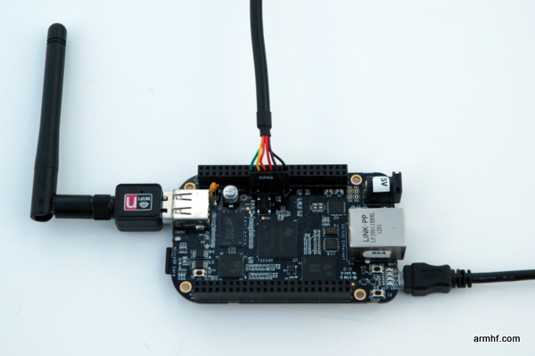
Figure 1 – BeagleBone Black with an FTDI TTL-232R-3V3 3.3V serial to USB attached to J1


Device Tree Overlay

The BeagleBone Black am335x-boneblack.dtb device file has only /dev/ttyO0 active by default. To enable the other UARTs, we could either modify this file or create an overlay (.dtbo) file to adjust this behavior at runtime. I opted to go with the .dtbo overlay approach. The compiled files and their proper application are noted in the section below.

Figure 2 shows the connection between the board doing the monitoring (top) using UART4, RX pin P9-11 and TX pin P9-13. It is connected to the board being monitored (bottom) via its UART0 serial debug port at J1. Note that J1 has six pins, but only three are active: pin 1: ground, RX pin 4 and TX pin 5. In this case the TX is tied to RX and vice-versa (TX:P9-13 to RX:J1-4 and RX:P9-11 to TX:J1-5).

BeagleBone Serial Debug

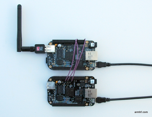
Figure 2 – BeagleBone Black serial J1 attached to BeagleBone Black ttyO4

Install and start minicom (apt-get install minicom) and launch it in setup mode (minicom -s). Select Serial port setup and change the Serial Device to /dev/ttyO4 (or whatever port you are using). Note that Hardware Flow Control is on by default and should be turned off.

That’s it. You should now be seeing the login screen of the other BeagleBone Black:

Welcome to minicom 2.5

OPTIONS: I18n 
Compiled on Dec  7 2011, 12:04:29.
Port /dev/ttyO4

Press CTRL-A Z for help on special keys                      

Ubuntu 12.04.2 LTS ubuntu-armhf ttyO0                        

ubuntu-armhf login: 


Serial UART Device Tree Overlay Files

The most difficult part was figuring out how to build the device tree overlay files. To build the overlay, use the unmodified device tree compiler available in the Ubuntu packages (apt-get install device-tree-compiler). Googling around, many examples are Ångström based that use /plugin/ and had a command-line option -@ that Ubuntu stock device tree compiler does support.  By decompiling an existing overlay file it is not too difficult to see how the parameters are defined within the file.  Below are overlay files for the various serial ports of the BeagleBone Black.

Copy the following .dtbo overlay files to the /lib/firmware directory and apply them after each boot with the command: echo ttyO1_armhf.com > /sys/devices/bone_capemgr*/slots

Note 1: ttyO3 does not have an RX pinout (it is tied to the TDA19988 HDMI chip)
Note 2: ttyO5 shares pins with the HDMI overlay – both cannot be active at the same time
Note 3: ttyO0 is available on J1 and does not require an overlay

After applying all four of the .dtbo files, you should see something like:

root@ubuntu-armhf:/# ll /dev/ttyO*
crw-rw---- 1 root tty     249, 0 Jan  1  2000 /dev/ttyO0
crw-rw---- 1 root dialout 249, 1 Jun 17 18:16 /dev/ttyO1
crw-rw---- 1 root dialout 249, 2 Jun 17 18:16 /dev/ttyO2
crw-rw---- 1 root dialout 249, 4 Jun 17 18:16 /dev/ttyO4
crw-rw---- 1 root dialout 249, 5 Jun 17 18:16 /dev/ttyO5
root@ubuntu-armhf:/# 


Serial UART Address and Configuration

Below are the notes from cross-referencing the BeagleBone Black System Reference Manual, the TI AM335x Datasheet, and the TI AM335x Technical Reference Manual. Take some time to review these manuals for yourself – several websites are out there with inaccurate information and transcription errors, so it pays to double-check. It is always more frustrating and challenging when multiple issues exist in code; this is one easy thing to get right. Also, don’t forget to examine the kernel log dmesg after trying to load an overlay file – many times the kernel will tell you exactly what is wrong.


UART0: 0x44E0_9000 (/dev/ttyO0)
   TX: 0x174 0x00 (j1-p5)  (ZCZ-E16 UART0_TXD mode:0 [datasheet]) = (conf_uart0_txd 974h [TRM p1126] = 0x0174)
   RX: 0x170 0x20 (j1-p4)  (ZCZ-E15 UART0_RXD mode:0 [datasheet]) = (conf_uart0_rxd 970h [TRM p1126] = 0x0170)

UART1: 0x4802_2000 (/dev/ttyO1)
   TX: 0x184 0x00  (p9-24) (ZCZ-D15 UART1_TXD mode:0 [datasheet]) = (conf_uart1_txd 984h [TRM p1126] = 0x0184)
   RX: 0x180 0x20  (p9-26) (ZCZ-D16 UART1_RXD mode:0 [datasheet]) = (conf_uart1_rxd 980h [TRM p1126] = 0x0180)

UART2: 0x4802_4000 (/dev/ttyO2)
   TX: 0x154 0x01  (p9-21) (ZCZ-B17 SPI0_D0   mode:1 [datasheet]) = (conf_spi0_d0   954h [TRM p1126] = 0x0154)
   RX: 0x150 0x21  (p9-22) (ZCZ-A17 SPI0_SCLK mode:1 [datasheet]) = (conf_spi0_sclk 950h [TRM p1126] = 0x0150)

UART3: 0x481A_6000 (/dev/ttyO3)
   TX: 0x164 0x01  (p9-42)       (ZCZ-C18 ECAP0_IN_PWM0_OUT mode:1 [datasheet]) = (conf_ecap0_in_pwm0_out 964h [TRM p1126] = 0x0164)
   RX: 0x188 0x21  (no breakout) (ZCZ-C17 I2C0_SDA          mode:1 [datasheet]) = (conf_i2c0_sda          988h [TRM p1126] = 0x0188) I2C0_SDA is tied to TDA19988

UART4: 0x481A_8000 (/dev/ttyO4)
   TX: 0x074 0x06  (p9-13) (ZCZ-U17 GPMC_WPn   mode:6 [datasheet]) = (conf_gpmc_wpn   874h [TRM p1124] = 0x0074)
   RX: 0x070 0x26  (p9-11) (ZCZ-T17 GPMC_WAIT0 mode:6 [datasheet]) = (conf_gpmc_wait0 870h [TRM p1124] = 0x0070)

UART5: 0x481A_A000 (/dev/ttyO5)
   TX: 0x0C0 0x04  (p8-37) (ZCZ-U1 LCD_DATA8 mode:4 [datasheet]) = (conf_lcd_data8 8C0h [TRM p1125] = 0x00C0)
   RX: 0x0C4 0x24  (p8-38) (ZCZ-U2 LCD_DATA9 mode:4 [datasheet]) = (conf_lcd_data9 8C4h [TRM p1125] = 0x00C4)
Posted in BeagleBone Black, Device Tree, HowTo Tagged with:

Using BeagleBone Black GPIOs

To control digital input / outputs for the BeagleBone Black, you can use the facilities exposed by the kernel in the /sys/class/gpio directory. Note that the BeagleBone White pinouts are different from the BeagleBone Black. Also note that the GPIOs available on the BBW have changed between revisions, so be certain to get the proper technical reference manual for your actual board revision.

After boot, nothing is exported for use, but we do see the four GPIO controllers (gpio0, gpio1, gpio2, and gpio3):

# ls -al /sys/class/gpio
total 0
drwxr-xr-x  2 root root    0 May 26 15:40 .
drwxr-xr-x 45 root root    0 Jan  1  2000 ..
--w-------  1 root root 4096 May 26 15:48 export
lrwxrwxrwx  1 root root    0 May 26 15:45 gpiochip0 -> ../../devices/virtual/gpio/gpiochip0
lrwxrwxrwx  1 root root    0 May 26 15:45 gpiochip32 -> ../../devices/virtual/gpio/gpiochip32
lrwxrwxrwx  1 root root    0 May 26 15:45 gpiochip64 -> ../../devices/virtual/gpio/gpiochip64
lrwxrwxrwx  1 root root    0 May 26 15:45 gpiochip96 -> ../../devices/virtual/gpio/gpiochip96
--w-------  1 root root 4096 May 26 15:45 unexport

Note that each GPIO controller is offset by 32 from the previous (0, 32, 64, 96) — more on this later.

Not all GPIO pins are available by default. A lot of frustration may come from not knowing this — sometimes when it appears that all should be working, it does not. The microcontroller needs to be reconfigured to enable some of the pin modes. To understand what may be available, you need to study table 10 on page 70 for the P8 header and table 11 on page 72 for the P9 header in the BeagleBone Black System Reference Manual. Pay close attention to which header is P8 and which is P9 (page 68) because they feel backwards to me.

In this example, I will export P9 header GPIO pins 12, 14, 15, 16. Referencing page 72 mode 7 column, it shows pin 12 to be gpio1[28], pin 14 to be gpio1[18], pin 15 to be gpio1[16], pin 16 to be gpio1[19]. All of these pins are on the gpio1 controller (gpiochip32). To get to the GPIO number that should be exported from the kernel, we must add on 32 to each GPIO (64 for gpio2, and 96 for gpio3). Therefore gpio1[28] = 32 + 28 = 60. I will just do all the math here and we will refer to them by the kernel nomenclature and stop with the gpio1[x] business as it gets confusing.

pin 12 --> gpio60
pin 14 --> gpio50
pin 15 --> gpio48
pin 16 --> gpio51

Now that we have a relationship between the P9 header physical pins and what the kernel is calling them, we can begin configuration. To make this example easy to follow, I am just going to use bash scripts, but all of the same principles apply to the file manipulation APIs in your favorite language.

In this example, we will be configuring all four pins to be digital outputs. To do so, we need to copy the gpio number we want to export into the kernel gpiolib /sys/class/gpio/export file.

echo 48 > /sys/class/gpio/export
echo 50 > /sys/class/gpio/export
echo 51 > /sys/class/gpio/export
echo 60 > /sys/class/gpio/export

Afterward we can see there are four new subdirectories for each of the gpios:

# ls -al /sys/class/gpio
total 0
drwxr-xr-x 2 root root    0 May 26 15:40 ./
drwxr-xr-x 45 root root   0 Jan  1  2000 ../
--w------- 1 root root 4096 May 26 16:25 export
lrwxrwxrwx 1 root root    0 May 26 16:25 gpio48 -> ../../devices/virtual/gpio/gpio48/
lrwxrwxrwx 1 root root    0 May 26 16:25 gpio50 -> ../../devices/virtual/gpio/gpio50/
lrwxrwxrwx 1 root root    0 May 26 16:25 gpio51 -> ../../devices/virtual/gpio/gpio51/
lrwxrwxrwx 1 root root    0 May 26 16:25 gpio60 -> ../../devices/virtual/gpio/gpio60/
lrwxrwxrwx 1 root root    0 May 26 15:45 gpiochip0 -> ../../devices/virtual/gpio/gpiochip0/
lrwxrwxrwx 1 root root    0 May 26 15:45 gpiochip32 -> ../../devices/virtual/gpio/gpiochip32/
lrwxrwxrwx 1 root root    0 May 26 15:45 gpiochip64 -> ../../devices/virtual/gpio/gpiochip64/
lrwxrwxrwx 1 root root    0 May 26 15:45 gpiochip96 -> ../../devices/virtual/gpio/gpiochip96/
--w------- 1 root root 4096 May 26 15:45 unexport

And the contents of one of the gpio subdirectories:

# ls -alH /sys/class/gpio/gpio48
total 0
drwxr-xr-x  3 root root    0 May 26 16:25 .
drwxr-xr-x 10 root root    0 May 26 15:45 ..
-rw-r--r--  1 root root 4096 May 26 16:29 active_low
-rw-r--r--  1 root root 4096 May 26 16:29 direction
-rw-r--r--  1 root root 4096 May 26 16:29 edge
drwxr-xr-x  2 root root    0 May 26 16:29 power
lrwxrwxrwx  1 root root    0 May 26 16:25 subsystem -> ../../../../class/gpio
-rw-r--r--  1 root root 4096 May 26 16:25 uevent
-rw-r--r--  1 root root 4096 May 26 16:29 value

There are several configuration options available to each gpio. I suggest you read the Linux GPIO Interfaces manual for all of the details. I am only covering the basics here, and the Linux GPIO Interfaces manual is a very important read to understanding Linux gpio control.

Next we must specify if the exported gpio is input or output. It does not make sense to configure anything else ahead of this and as far as I know, the kernel doesn’t let you do anything else with it until you set the gpio as input or output.

To set a gpio as output, we set its direction as in or out. For outputs there is an alternative nomenclature where output direction can be set instead as high or low to help with glitch free operation. I’ll use this nomenclature:

echo high > /sys/class/gpio/gpio48/direction
echo high > /sys/class/gpio/gpio50/direction
echo high > /sys/class/gpio/gpio51/direction
echo high > /sys/class/gpio/gpio60/direction

Pins 12, 14, 15, 16 are now configured as outputs and are currently high — these pins will now be reading 3.3v. Do not use 5v TTL logic parts or you will damage the board.

Finally, we will set the pins low which will depower them:

echo 0 > /sys/class/gpio/gpio48/value
echo 0 > /sys/class/gpio/gpio50/value
echo 0 > /sys/class/gpio/gpio51/value
echo 0 > /sys/class/gpio/gpio60/value

Putting this all together, this script will configure and run a binary counter that will overflow and start at zero again. It is kind of cool to watch if you hook relays up to the board.

#!/bin/bash -e

if [ ! -d /sys/class/gpio/gpio48 ]; then echo 48 > /sys/class/gpio/export; fi
if [ ! -d /sys/class/gpio/gpio50 ]; then echo 50 > /sys/class/gpio/export; fi
if [ ! -d /sys/class/gpio/gpio51 ]; then echo 51 > /sys/class/gpio/export; fi
if [ ! -d /sys/class/gpio/gpio60 ]; then echo 60 > /sys/class/gpio/export; fi

echo low > /sys/class/gpio/gpio48/direction
echo low > /sys/class/gpio/gpio50/direction
echo low > /sys/class/gpio/gpio51/direction
echo low > /sys/class/gpio/gpio60/direction

for (( i=0 ; ; ++i ))
do
   if (( i > 0x0f )); then
      i=0
      printf '\n[press  + c to stop]\n\n'
   fi

   bit0=$(( (i & 0x01) > 0 ))
   bit1=$(( (i & 0x02) > 0 ))
   bit2=$(( (i & 0x04) > 0 ))
   bit3=$(( (i & 0x08) > 0 ))
   echo $bit3 $bit2 $bit1 $bit0

   echo $bit0 > /sys/class/gpio/gpio60/value
   echo $bit1 > /sys/class/gpio/gpio50/value
   echo $bit2 > /sys/class/gpio/gpio48/value
   echo $bit3 > /sys/class/gpio/gpio51/value

   sleep .2
done


The Script in Action

Posted in BeagleBone Black, HowTo

Expanding Linux Partitions: Part 2 of 2

As shown in Part 1 of this article, extracting Linux from a pre-made .img file can result in unused space at the end of the uSD card. Depending on the size of the uSD card, this could leave a significant amount of space left unused. This article shows how to repartition the uSD card to utilize all of the space on the uSD card. This can be done on an unmounted filesystem or even on a live filesystem. In the example below, the live filesystem of a BeagelBone Black (running the Debian Wheezy image) will be resized to take advantage of the full 4GB of space available on the uSD card used in this example.

Step 1: Start fdisk


To get started, list the volumes available on a BeagleBone Black that is booted from a uSD card:

root@debian-armhf:/# ls -l /dev/mmcblk*
brw-rw---T 1 root floppy 179, 0  Jan 1 2000 /dev/mmcblk0
brw-rw---T 1 root floppy 179, 1  Jan 1 2000 /dev/mmcblk0p1
brw-rw---T 1 root floppy 179, 2  Jan 1 2000 /dev/mmcblk0p2
brw-rw---T 1 root floppy 179, 8  Jan 1 2000 /dev/mmcblk1
brw-rw---T 1 root floppy 179, 16 Jan 1 2000 /dev/mmcblk1boot0
brw-rw---T 1 root floppy 179, 24 Jan 1 2000 /dev/mmcblk1boot1
brw-rw---T 1 root floppy 179, 9  Jan 1 2000 /dev/mmcblk1p1
brw-rw---T 1 root floppy 179, 10 Jan 1 2000 /dev/mmcblk1p2

The listing above shows an external uSD card is currently booted as indicated by the /dev/mmcblk0 entries and the lack of /dev/mmcblk0boot entries. When booted from the internal eMMC, the device with the /dev/mmcblk1boot entries would instead be at the device zero location as shown here:

root@debian-armhf:/# ls -l /dev/mmcblk*
brw-rw---T 1 root floppy 179, 0  Jan 1 2000 /dev/mmcblk0
brw-rw---T 1 root floppy 179, 1  Jan 1 2000 /dev/mmcblk0p1
brw-rw---T 1 root floppy 179, 16 Jan 1 2000 /dev/mmcblk0boot0
brw-rw---T 1 root floppy 179, 24 Jan 1 2000 /dev/mmcblk0boot1
brw-rw---T 1 root floppy 179, 2  Jan 1 2000 /dev/mmcblk0p2
brw-rw---T 1 root floppy 179, 8  Jan 1 2000 /dev/mmcblk1
brw-rw---T 1 root floppy 179, 9  Jan 1 2000 /dev/mmcblk1p1
brw-rw---T 1 root floppy 179, 10 Jan 1 2000 /dev/mmcblk1p2

To get started, run fdisk /dev/mmcblk0 to examine the partitioning of the external uSD card that is currently booted:

root@debian-armhf:/# fdisk /dev/mmcblk0

Command (m for help): p

Disk /dev/mmcblk0: 3947 MB, 3947888640 bytes
4 heads, 16 sectors/track, 120480 cylinders, total 7710720 sectors
Units = sectors of 1 * 512 = 512 bytes
Sector size (logical/physical): 512 bytes / 512 bytes
I/O size (minimum/optimal): 512 bytes / 512 bytes
Disk identifier: 0x80000000

        Device Boot      Start         End      Blocks   Id  System
/dev/mmcblk0p1   *        2048        4095        1024    1  FAT12
/dev/mmcblk0p2            4096     3751935     1873920   83  Linux

Command (m for help): 

Take a moment to examine what fdisk is reporting. The first line indicates that the uSD card is 3947888640 bytes in size. The 4th line reports the sector size to be 512 bytes. Some quick math shows that 3947888640 bytes / 512 bytes per sector = 7710720 sectors as is also reported on the second line. The default “block” size is 1024 bytes, but it does not actually report this unit anywhere. The Start and End columns are reporting 512 byte sectors, and the Blocks column is reporting 1024 byte blocks. The way this .img is partitioned makes the relationship easy to see in this case, but it would not be immediately apparent if this were a large hard disk and the numbers were not as magic. The starting block of the partition table at position 2048 reveals that blocks 0-2047 are not being used for user data. This amounts to a full megabyte (2048 * 512 bytes per block = 1048576 bytes), and this is the default of fdisk. The first partition is 2048 sectors in size, or 1024K, which confirms the block size being 1K.

To calculate the total size of the space used on the disk,  there are 2048 sectors at the head reserved for partitioning, 2048 sectors in mmcblk0p1, and 3,751,936 sectors in mmcblk0p2 for a total of 3,756,032 sectors. With each sector using 512 bytes, this totals 1,923,088,384 bytes. The choice of 1,923,088,384 bytes was used to make this image the exact size of the BeagleBone’s available eMMC space (note that 1,923,088,384 bytes / 1024^2 = 1834 MB). It is also a good size because not all external 2 GB uSD cards are exactly 2048 * 1024^2 in size. Having it a bit under 2 GB makes it a sure fit.

Repartitioning the disk is rather easy since fdisk will prompt with smart default choices. The steps below will begin by deleting partition 2, then recreate it as a larger size, and finally write the new table to the disk only at the end. Notice the emphasis on the last part: No changes are actually committed to disk along the way — only by pressing ‘w’ at the end will cause changes to be written. If you make a mistake or panic, just hit ‘q’ to quit and no changes will have been made.


Step 2: Delete Partition 2


Press ‘d’ for delete and ‘2’ for partition 2.

Command (m for help): p

Disk /dev/mmcblk0: 3947 MB, 3947888640 bytes
4 heads, 16 sectors/track, 120480 cylinders, total 7710720 sectors
Units = sectors of 1 * 512 = 512 bytes
Sector size (logical/physical): 512 bytes / 512 bytes
I/O size (minimum/optimal): 512 bytes / 512 bytes
Disk identifier: 0x80000000

        Device Boot      Start         End      Blocks   Id  System
/dev/mmcblk0p1   *        2048        4095        1024    1  FAT12
/dev/mmcblk0p2            4096     3751935     1873920   83  Linux

Command (m for help): d
Partition number (1-4): 2

Command (m for help): p

Disk /dev/mmcblk0: 3947 MB, 3947888640 bytes
4 heads, 16 sectors/track, 120480 cylinders, total 7710720 sectors
Units = sectors of 1 * 512 = 512 bytes
Sector size (logical/physical): 512 bytes / 512 bytes
I/O size (minimum/optimal): 512 bytes / 512 bytes
Disk identifier: 0x80000000

        Device Boot      Start         End      Blocks   Id  System
/dev/mmcblk0p1   *        2048        4095        1024    1  FAT12

Command (m for help): 


Step 3: Recreate Partition 2


Press ‘n’ for new, ‘p’ for primary, and ‘2’ for partition 2. Specify start and end sectors for the new partition — just select the default values by pressing enter. In fact, outside of the the first ‘n’ they were all default choices and pressing enter alone to confirm the choice is all that is needed.

Command (m for help): n
Partition type:
   p   primary (1 primary, 0 extended, 3 free)
   e   extended
Select (default p): p
Partition number (1-4, default 2): 2
First sector (4096-7710719, default 4096): 
Using default value 4096
Last sector, +sectors or +size{K,M,G} (4096-7710719, default 7710719): 
Using default value 7710719

Command (m for help): p

Disk /dev/mmcblk0: 3947 MB, 3947888640 bytes
4 heads, 16 sectors/track, 120480 cylinders, total 7710720 sectors
Units = sectors of 1 * 512 = 512 bytes
Sector size (logical/physical): 512 bytes / 512 bytes
I/O size (minimum/optimal): 512 bytes / 512 bytes
Disk identifier: 0x80000000

        Device Boot      Start         End      Blocks   Id  System
/dev/mmcblk0p1   *        2048        4095        1024    1  FAT12
/dev/mmcblk0p2            4096     7710719     3853312   83  Linux

Command (m for help): 

That is it!  Select ‘w’ to commit the changes to the uSD card.  Notice that the partition table in this example was “busy” so a reboot was needed to cause the changes to be reflected.  Even if it were not busy, it seems like it could be a good idea to reboot at this point if you want to be extra safe.

Command (m for help): w

The partition table has been altered!

Calling ioctl() to re-read partition table.

WARNING: Re-reading the partition table failed with error 16: Device or resource busy.
The kernel still uses the old table. The new table will be used at
the next reboot or after you run partprobe(8) or kpartx(8)
Syncing disks.
root@debian-armhf:/# reboot


Step 4: Expand the Filesystem


This is the last step. Now that the second partition is larger, expand the filesystem to match the larger partition using resize2fs.


root@debian-armhf:/# df
Filesystem     1K-blocks   Used Available Use% Mounted on
rootfs           1811704 740184    977824  44% /
/dev/root        1811704 740184    977824  44% /
devtmpfs          253920      0    253920   0% /dev
tmpfs              50816    216     50600   1% /run
tmpfs               5120      0      5120   0% /run/lock
tmpfs             101620      0    101620   0% /run/shm
/dev/mmcblk0p1      1004    474       530  48% /boot/uboot
root@debian-armhf:/# 

root@debian-armhf:/# resize2fs /dev/mmcblk0p2 
resize2fs 1.42.5 (29-Jul-2012)
Filesystem at /dev/mmcblk0p2 is mounted on /; on-line resizing required
old_desc_blocks = 1, new_desc_blocks = 1
The filesystem on /dev/mmcblk0p2 is now 963328 blocks long.

root@debian-armhf:/# df
Filesystem     1K-blocks   Used Available Use% Mounted on
rootfs           3761680 741096   2851404  21% /
/dev/root        3761680 741096   2851404  21% /
devtmpfs          253920      0    253920   0% /dev
tmpfs              50816    216     50600   1% /run
tmpfs               5120      0      5120   0% /run/lock
tmpfs             101620      0    101620   0% /run/shm
/dev/mmcblk0p1      1004    474       530  48% /boot/uboot
root@debian-armhf:/# 


Summary


All of the space on the uSD card is now available for use. To recap:

# fdisk /dev/mmcblk0
d
2
n
p
2
4096

w

# resize2fs /dev/mmcblk0p2

Part 1

Posted in BeagleBone Black, eMMC, HowTo, Partitioning

BeagleBone Black GA Angstrom Image

Before booting the BeagleBone Black for the first time, you may want to snap an image of the unbooted the Angstrom load from NVRAM in its virgin state for future reference.  To do this, we need a microSD card to boot the BeagleBone Black and snap the image.  The BeagleBone Black Ubuntu image available on the downloads page will work nicely for this purpose.  Just cat the image using these instructions, then boot it from microSD by holding down the user button at power-on.  Once booted, ssh into the device, sudo su to root, and get started.
 
If you need the original image you can find it located on the downloads page.
 
The internal NVRAM will be seen as the /dev/mmcblk1 device.

# ll /dev/mmcblk*
brw-rw---- 1 root disk 179,  0 Apr 30 03:24 /dev/mmcblk0
brw-rw---- 1 root disk 179,  1 Apr 30 03:24 /dev/mmcblk0p1
brw-rw---- 1 root disk 179,  2 Apr 30 03:24 /dev/mmcblk0p2
brw-rw---- 1 root disk 179,  8 Apr 30 03:24 /dev/mmcblk1
brw-rw---- 1 root disk 179, 16 Apr 30 03:24 /dev/mmcblk1boot0
brw-rw---- 1 root disk 179, 24 Apr 30 03:24 /dev/mmcblk1boot1
brw-rw---- 1 root disk 179,  9 Apr 30 03:24 /dev/mmcblk1p1
brw-rw---- 1 root disk 179, 10 Apr 30 03:24 /dev/mmcblk1p2

Capture the image using the dd command.

# dd bs=1M count=1832 if=/dev/mmcblk1 | xz -cz > ./bbb_angstrom_ga.tar.xz

Now is a good time to go get a cup of coffee because this takes a while.
In the future if you need to restore the image, just do the reverse:

# xz -cd ./bbb_angstrom_ga.tar.xz > /dev/mmcblk1


Posted in BeagleBone Black, eMMC, HowTo

Expanding Linux Partitions: Part 1 of 2

When installing Linux by unpacking .tar files into empty boot and root file system partitions, you get to decide how the partitions will lay out. When extracting Linux from a raw image file, the partition table is already defined and may not fit your needs and likely does not utilize all space available on the microSD card. For example, the Ubuntu 12.10 .img file available for the BeagleBone Black is sized exactly at 1832MB so it is able to precisely fit into the BeagleBone Black’s internal eMMC storage.

If you are extracting this image to a microSD card, you will likely have a significant amount of unused space available. With many inexpensive microSD cards sporting capacities of 4GB to 8GB (or more), the afore mentioned 1.8GB partition layout leaves us with some additional work to be done. Fortunately, it is not difficult to take advantage of all available space. I am going to review two different methods for achieving this goal.

The first method may not be immediately obvious, but we can create an additional third partition and mount it into the filesystem at boot time. There are a few compelling reasons for selecting this method. If you are planning to install a graphical desktop you will want to create a swap partition and you should set aside space for this. Additionally, if you are intending to allow external sources to upload information via a web browser or FTP, it is possible to have a volume run out of space. Having a dedicated upload and logging var volume will prevent uploads or excessive logging from utilizing more than a predetermined amount of space. Similar benefits can be realized buy mounting the home directory this way as well.

The second technique takes advantage of Linux’s ability to expand a partition in-place on a booted system so long as no data exists beyond the end of that partition. Afterward, the ext2, ext3, or ext4 filesystem can be expanded using resize2fs to use this new available space at the end of the volume.


Adding a Partition

In this case we are going to dump all extra space into a single storage volume where we can mount from /etc/fstab as desired. The example is generic enough to be adapted for specific use cases.


Step 1: Start fdisk


# fdisk /dev/mmcblk0

Command (m for help): p

Disk /dev/mmcblk0: 15.7 GB, 15719727104 bytes
4 heads, 16 sectors/track, 479728 cylinders, total 30702592 sectors
Units = sectors of 1 * 512 = 512 bytes
Sector size (logical/physical): 512 bytes / 512 bytes
I/O size (minimum/optimal): 512 bytes / 512 bytes
Disk identifier: 0x00000000

        Device Boot      Start         End      Blocks   Id  System
/dev/mmcblk0p1   *          63       65598       32768    c  W95 FAT32 (LBA)
/dev/mmcblk0p2           65599     3751935     1843168+  83  Linux

Command (m for help): 

In this case notice that the prepackaged 1.8GB image has been expanded onto a 16GB microSD card (notice the 15.7 GB at the top). To make a new /dev/mmcblk0p3 parition we type ‘n’ for new ‘p’ for primary (the default), 3 for the 3rd partition (the default), select the default first sector (3751936 in my case) and the default value for the last sector to use all remaining space. Don’t worry about mistakes yet, <ctrl> + c or ‘q’ for quit will exit the program leaving your microSD unchanged.

Command (m for help): n
Partition type:
   p   primary (2 primary, 0 extended, 2 free)
   e   extended
Select (default p): 
Using default response p
Partition number (1-4, default 3): 
Using default value 3
First sector (3751936-30702591, default 3751936): 
Using default value 3751936
Last sector, +sectors or +size{K,M,G} (3751936-30702591, default 30702591): 
Using default value 30702591

Command (m for help):

If you want to save space for a swap partition, use the +size notation for the end value. For example +12G for a 12GB partition. At this point it is wise to review your work before committing changes by using the ‘p’ command to print the current configuration choices. When all looks correct, ‘w’ will commit your changes to disk and exit.

At this point we should be able to see the new partition as a device.

# ls -l /dev/mmcblk0*
brw-rw---- 1 root disk 179,  0 Apr 30 02:21 /dev/mmcblk0
brw-rw---- 1 root disk 179,  1 Apr 28 23:47 /dev/mmcblk0p1
brw-rw---- 1 root disk 179,  2 Apr 28 23:47 /dev/mmcblk0p2
brw-rw---- 1 root disk 179,  3 Apr 30 02:22 /dev/mmcblk0p3

We now have a partition ready for a filesystem.


Step 2: Format the Partition


To format as an ext4 volume, use mkfs.ext4. Likewise, to format as an ext3 volume, use mkfs.ext3. Note that the -L option sets the volume label and is optional.

# mkfs.ext4 -L "storage" /dev/mmcblk0p3
mke2fs 1.42.5 (29-Jul-2012)
Discarding device blocks: done                            
Filesystem label=storage
OS type: Linux
Block size=4096 (log=2)
Fragment size=4096 (log=2)
Stride=0 blocks, Stripe width=0 blocks
843776 inodes, 3368832 blocks
168441 blocks (5.00%) reserved for the super user
First data block=0
Maximum filesystem blocks=3451912192
103 block groups
32768 blocks per group, 32768 fragments per group
8192 inodes per group
Superblock backups stored on blocks: 
	32768, 98304, 163840, 229376, 294912, 819200, 884736, 1605632, 2654208

Allocating group tables: done                            
Writing inode tables: done                            
Creating journal (32768 blocks): done
Writing superblocks and filesystem accounting information: done   


Step 3: Mount the Volume


The next step is to create a location in the filesystem to mount the new volume. Create a /mnt/storage directory for this purpose and mount the volume.

# mkdir /mnt/storage
# mount /dev/mmcblk0p3 /mnt/storage
# df
Filesystem     1K-blocks   Used Available Use% Mounted on
/dev/mmcblk0p2   1781432 541188   1148088  33% /
udev              252780      4    252776   1% /dev
tmpfs             101648    248    101400   1% /run
none                5120      0      5120   0% /run/lock
none              254112      0    254112   0% /run/shm
none              102400      0    102400   0% /run/user
/dev/mmcblk0p1     32686   6134     26552  19% /boot/uboot
/dev/mmcblk0p3  13132408  32904  12425740   1% /mnt/storage

Place an entry in /etc/fstab auto-mount the new volume at boot time.

proc /proc proc defaults 0 0
/dev/mmcblk0p2      /              auto   errors=remount-ro   0   1
/dev/mmcblk0p1      /boot/uboot    auto   defaults            0   0
/dev/mmcblk0p3      /mnt/storage   auto   defaults            0   0

Each time the BeagleBone Black is booted, it will auto-mount the new volume.


Step 4: Additional Mount Points Using Bind Mounts


Having a heap of storage sitting off at /mnt/storage isn’t the most useful thing in the world. We want to have meaningful subdirectories of the filesystem using this store. For this we use bind mounts. This allows us to move the users’ /home directory to the new storage partition. Notice we create a new empty /home directory for the one we move.

# mv /home /mnt/storage
# mkdir /home

Add the bind mount to /etc/fstab.

proc /proc proc defaults 0 0
/dev/mmcblk0p2      /              auto   errors=remount-ro   0   1
/dev/mmcblk0p1      /boot/uboot    auto   defaults            0   0
/dev/mmcblk0p3      /mnt/storage   auto   defaults            0   0
/mnt/storage/home   /home          none   defaults,bind       0   0

To see the bind mounts specify the -a option for df.

# df -a
Filesystem        1K-blocks   Used Available Use% Mounted on
/dev/mmcblk0p2      1781432 541108   1148168  33% /
proc                      0      0         0    - /proc
sysfs                     0      0         0    - /sys
none                      0      0         0    - /sys/fs/fuse/connections
none                      0      0         0    - /sys/kernel/debug
none                      0      0         0    - /sys/kernel/security
udev                 252780      4    252776   1% /dev
devpts                    0      0         0    - /dev/pts
tmpfs                101648    220    101428   1% /run
none                   5120      0      5120   0% /run/lock
none                 254112      0    254112   0% /run/shm
none                 102400      0    102400   0% /run/user
/dev/mmcblk0p1        32686   6134     26552  19% /boot/uboot
/dev/mmcblk0p3      1969936   3032   1865172   1% /mnt/storage
/mnt/storage/home   1969936   3032   1865172   1% /home

This can be done for other directories such as /tmp and /var as well.

In Part 2 of this article, I show how to expand the existing /dev/mmcblk0p2 volume in-place to achieve similar results.

Posted in BeagleBone Black, eMMC, HowTo, Partitioning

Node.js for the BeagleBone Black

node.js

To run node.js on the BeagleBone, it needs to be compiled from scratch or you can install a precompiled distribution available on the downloads page. While it seems to be more common to cross-compile for the ARM, I find it easier to natively compile it on the BeagleBone, but it does take a bit longer.

Note that I compile and install as root sudo su, so if you get any differing result, keep this in mind.


Step 1: Prerequisites

We will need a compiler to compile the node source. The build requires python for the configuration scripts and gcc for the actual code.

# apt-get install python
# apt-get install build-essential


Step 2: Download Node Source

Download the latest source code from the node.js website. At the time of writing it is version 0.10.5 so adjust this to the desired version. We will unpack it in the current directory. Specify the -C <path> option to extract it elsewhere.

# wget http://nodejs.org/dist/v0.10.5/node-v0.10.5.tar.gz
# tar xzvf node-v0.10.5.tar.gz


Step 3: Configure

At the time of this writing, there is a problem with the Google V8 Snapshot feature causing node to segmentation fault. Snapshotting helps node start faster and is not a big-deal feature; we will just compile without it.

# cd node-v0.10.5
# ./configure --without-snapshot
Result:
{ 'target_defaults': { 'cflags': [],
                       'default_configuration': 'Release',
                       'defines': [],
                       'include_dirs': [],
                       'libraries': []},
  'variables': { 'arm_fpu': 'vfpv3',
                 'arm_neon': 0,
                 'armv7': 1,
                 'clang': 0,
                 'gcc_version': 47,
                 'host_arch': 'arm',
                 'node_install_npm': 'true',
                 'node_prefix': '',
                 'node_shared_cares': 'false',
                 'node_shared_http_parser': 'false',
                 'node_shared_libuv': 'false',
                 'node_shared_openssl': 'false',
                 'node_shared_v8': 'false',
                 'node_shared_zlib': 'false',
                 'node_tag': '',
                 'node_unsafe_optimizations': 0,
                 'node_use_dtrace': 'false',
                 'node_use_etw': 'false',
                 'node_use_openssl': 'true',
                 'node_use_perfctr': 'false',
                 'node_use_systemtap': 'false',
                 'python': '/usr/bin/python',
                 'target_arch': 'arm',
                 'v8_enable_gdbjit': 0,
                 'v8_no_strict_aliasing': 1,
                 'v8_use_arm_eabi_hardfloat': 'true',
                 'v8_use_snapshot': 'false'}}
creating  ./config.gypi
creating  ./config.mk


Step 4: Compile

We are ready to compile. It is going to take about a half-hour to complete — go get a cup of coffee.

# make


Step 5: Verify

Now that the build has finished, we can verify that all looks well before we install it.

# ./node -e 'console.log("het werkt!");'
# ./node -v


Step 6: Install

Now that all looks well, we are ready install it.

# make install
Posted in BeagleBone Black, HowTo Tagged with: